
Progress and Challenges in the Cellular Industry and 5G
Qi Bi, China Telecom
IEEE Future Networks Tech Focus, Volume 4, Issue 1, November 2020
Abstract
When compared with the 4G-LTE, 5G has made impressive progress in many technological areas including the spectral efficiency, user data rate, and transmission delay. It promises to support mMTC and uRLLC in addition to the traditional eMBB. However, by examining the 5G system operating in the field, this paper intends to provide insights that show different sides of 5G that we have not seen, and uncover issues that need to be addressed in the future.
1. Progress made by 5G
The technology of 5G has made impressive progress in many areas including the spectral efficiency, data rate, transmission delay, and system capacity [1-3], despite difficulties [4] The following table shows the 5G targets as provided by ITU [5]. While the metrics of this table are well advertised by the media and business conferences, a little known secret is that some of these metrics were not actually achieved. As can be seen from the table, the 8 metrics could be divided into three categories: achieved, achievable and not achieved.
|
Achieved by 5G |
Achievable by 5G |
Not Achieved |
||||||
|
mobility |
User speed |
Efficiency |
Density |
Connection |
Delay |
Energy |
Peak rate |
|
|
4G |
350Km/h |
10 Mbps |
1x |
0.1 Mbps/m2 |
100,000/km2 |
10ms |
1x |
1Gbps |
|
5G |
500Km/h |
100Mbps |
3x |
10 Mbps/km2 |
1million/Km2 |
1ms |
100x |
20Gbps |
When labeled as achievable, this means that the target has not yet been achieved because there is no need. When the system capacity and density requirements increase, the target can be achieved by simply investing more money to purchase more equipment.
In the “not achieved” category, there exists the energy efficiency and peak rate targets. The target for 100 times the efficiency was vague to begin with and was overly optimistic because it was based purely on theoretical wishes. The 20Gbps peak rate, however, is based on the assumption that more than 1GHz bandwidth is available and that the peak rate spectral efficiency would be adequate. Currently, only 100-200MHz are typically available for sub-6GHz bands and only about 800MHz are available for 28GHz bands. Further, the peak rate efficiency in high bands was significantly lower due to the limitations on the chipset and hardware processing power.
In spite of the peak rate gap, 5G has made significant progress in terms of Shannon’s information theory guidance [6-7] as given in the following chart.
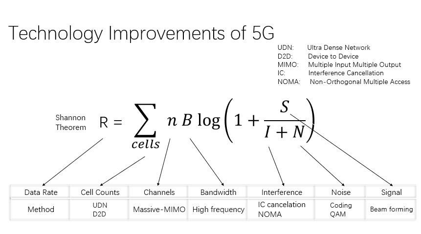
Figure 1
By examining each of the innovations as seen above, massive MIMO can be identified to provide most of the gains for 5G. The spectral efficiency and the peak rate efficiency of the wireless system evolution are provided in the following two charts.
In China, China Telecom has been granted 100MHz license in the 3.5GHz spectrum. 5G trials in this band were carried out and the achievable peak rates in 100MHz is provided in the following chart, which shows that about 1.5Gbps can be expected for the DL and less than 300Mbps may be obtainable for the UL under the best RF conditions if the system has only a single user.
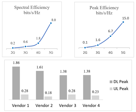
Figure 2
2. Challenges of 5G
While progress made by 5G has been impressive, 5G also faces many challenges [8] as we shall discuss below.
2.1. Revenue challenge of 5G
While the progress made by 5G is impressive, its deployment is not believed to improve the financial income of operators in terms of ARPU, as was the case for the past generations. This assumption can be easily derived from the figure below in which the historical ARPU curve was provided by one of the world’s largest operators from the second largest economy in the world. In the above figure, it can be observed that China Telecom’s ARPU followed a downward slope even after the company aggressively invested in new system evolution from 2G to 3G and then to 4G that improved the data rate immensely for large number of users. Consequently, it is reasonable to predicted that the impressive data rate improvement from 5G will unlikely to increase the ARPU for China Telecom. This trend appears to be applicable to operators worldwide.
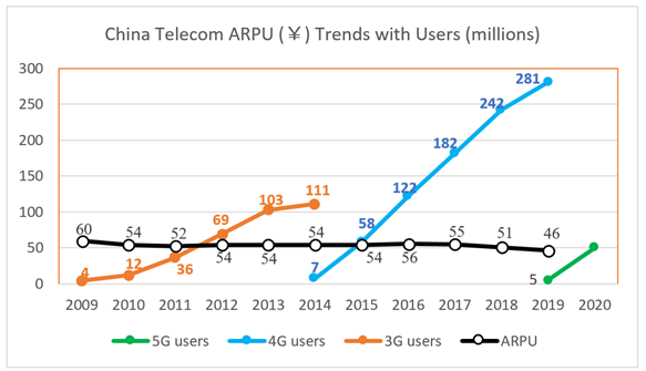
Figure 3
The above facts prompted efforts to expand 5G capabilities beyond the traditional eMBB service. These capabilities include mMTC and uRLLC. Despite good intentions, the progress made on the ground is not as satisfactory for reasons as will be discussed in the follow sections.
2.2. Cost challenge for 5G
One of the main features for 5G is the massive MIMO that has significantly improved the spectral efficiency and data rate. As a result of the massive MIMO, the cost of the 5G base station is more than two times that of 4G. Due to the fact that 5G will be operating at the higher band, its system would require more base stations, which would put pressure on the CAPEX investments of operators. To accommodate the wider band for 5G, a higher transmission power of 200W was adopted to maintain the power density similar to that of 4G that uses a typical 60W. This 3-fold increase in transmission power will likely translate into 3 times the electric bill required by each base station for 5G. Since the electric expense is a significant percentage of an operator’s OPEX, this electric consumption is a serious issue that will need to be dealt with in the future.
2.3. Millimeter wave challenge of 5G
In order to meet the growing demands for data rates and system capacity, next generation cellular systems have consistently moved to higher frequencies to satisfy the broader bandwidth requirements. For 5G, two frequency bands are defined as FR1 and FR2 where FR2 is the millimeter wave band. The propagation loss of the radio waves in a free space can be determined by the distance and transmission frequency as given in the following formula [9]:
where c is a constant, Dt is the transmit antenna gain, Dr is the receive antenna gain, f is the transmission frequency and d is the radius from the transmitter. When considering other propagation environments, the COST model [10] indicates that the exponent increases from 2 to about 3.5. From this, it can be determined that a ten-fold increase in frequency would result in a similar amount of decrease in the propagation radius if the pathloss of the system is kept the same for a similar QoS.
To counter this drastic radius reduction, antenna technology is typically used to increase the antenna gain by taking advantage of the fact that the size of the antenna is proportional to the wavelength. By keeping the antenna size about the same for each generation, the loss caused by being at the high bands can be partially compensated by increasing the number of antennas.
However, due to the fact that the antenna gain improvement requires an exponential increase in the number of antennas and the fact that the chipset complexity improvement for each generation cannot follow the required increase in the number of antennas, the number of base stations required to have ubiquitous coverage at the millimeter wave bands are costly prohibitive. Consequently, millimeter wave deployment is only considered for hot spot or for special applications such as fixed wireless application. This use case affects the volume of the millimeter wave base stations and therefore the cost of the system, which has made the millimeter wave deployment much less successful globally.
Another challenge of the millimeter wave deployment for 5G is a result of the world politics. As previously discussed, the drastic effect on coverage when moving to higher bands can be partially mitigated by increasing the number of antennas which would in turn increase the complexity and the cost of the system and devices. The trend in the industry is such that the ARPU and the device cost curves have remained flat for each generation.
For this reason, the common practice for keeping the cost in check is by handling the device complexity increase with the increase of the device volume in the markets. This strategy has worked in the past but may have hit a roadblock in the millimeter wave case. Due to the fact that the millimeter wave technology was initially used for satellite and military purposes similar to the GPS system, there are still export restrictions for millimeter wave devices that are no present for GPS technology. As a result, GPS has been successfully commercialized globally whereas the prevalence of the millimeter wave deployments for 5G may depend on the removal of the restrictions if the volume and cost of such deployments are expected to reach the desired level.
2.4. Transmission delay challenge in 5G
To achieve the expected high data rate for 5G, larger bandwidth is needed that can only be found in higher bands. As a result, time division duplex (TDD) is the prevailing choice over FDD because a paired spectrum is harder to find. However, one problem with the TDD is that the UL and DL need to take turns to transmit, introducing an additional link switch transmission delay. Furthermore, due to the fact that a time gap is needed between the UL and DL to allow signal transition, this switch between the UL and DL cannot be done too often in order to minimize the time gap for efficiency consideration. As a result, TDD would result in a non-negligible transmission delay depending on efficiency considerations.
As an example, China Telecom and China Union have jointly decided to use 2.5ms TDD configuration as a compromise between the delay and the capacity efficiency. This results in an additional link switch transmission delay of 2ms. From this example, it appears that even though the 5G standard has defined configurations that could meet the 1ms transmission target by ITU, in practice this target cannot be achieved in the real world due to capacity efficiency considerations. To support the 1ms target for uRLLC applications, China operators have deployed FDD systems that avoid the link switch delay. This, however, requires operators to deploy FDD systems for low delay applications in addition to the TDD system for high data rate eMBB applications.
2.5. Coverage and data rate challenge for 5G
In the previous section, it was discussed that the coverage shortcoming from moving to the higher bands could partially be compensated for by increasing the number of antennas. Another trend in the next generation system such as 5G is to move from FDD which uses the paired channel to TDD which uses a single band. This change in the duplex, however, introduces about 5 dB additional loss on the UL which would also need to be compensated.
To understand this, consider the TDD configuration as adopted by China Telecom and China Unicom for example. The time slot configuration is given in the following figure.
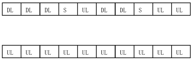
Figure 4: TDD time slots divided for DL and UL (Top), FDD time slots all for UL (Bottom)
In the above figure, each DL, UL or S time slot is 0.5ms. Each time slot consists of 14 sub-slots. For special time slot labeled as S, 10 of its 14 sub-slots are assigned to DL, 2 are assigned as gap sub-slots for transition, and 2 sub-slots are assigned for the UL. Therefore, the total UL sub-slots for TDD system are (3x14) + (2x2) = 46 out of 140, which is about 33% in time domain. In comparison, the transmission at 2.1GHz band using FDD can dedicate all time slots for UL transmission. If the maximum terminal transmits powers of both TDD and FDD are identical, clearly the receiver would lose 66% of time to accumulate the energy in the TDD case, resulting in about 5 dB loss for the TDD system when compared with that of the FDD system.
Currently most terminals are equipped with two simultaneous transmitters. While more than two are possible in the future, but two may still be a preferred choice for most handsets due to the cost consideration.
From the above figure, if the terminal assigns both transmitters to TDD operation, it could enjoy the 5G peak rate from the 100MHz bandwidth with two antenna MIMO technology, but it suffers a 5 dB coverage loss. If any of the two transmitters uses the FDD transmission mode with 20MHz bandwidth, the coverage gain is obtained at the cost of the data rate obtainable via two TDD transmitter antennas. To solve this dilemma, China Telecom proposed the use of multi-carrier time division duplex technique which combines the operation of the TDD with the FDD. With this proposal, the two transmitters are allowed to switch quickly at each 0.5ms boundary that is not possible for Release 15 of 5G. Time slots of 1, 2, 3, 4, 6, 7 and 8 are allowed to transmit the UL signals using FDD operation. At the time slot 5, 9, and 10, the two transmitters will all be assigned to TDD to take the advantage of 100MHz bandwidth. This combined TDD and FDD innovation from China Telecom solves this FDD and TDD dilemma and will be available in Release 16 of 5G [12-13].
2.6. mMTC challenge for 5G
Given the flat ARPU discussed previously, mMTC was the hope to provide additional revenue growth for operators. While this seems logic and attractive, the reality so far appears disappointing. The first attempt to support mMTC was done in 4G-LTE using the narrow band technology known as the NB-LTE or NB-IoT. China Telecom was the first operator in the world to have deployed the commercial NB-LTE system in large scale. So far, China Telecom has not yet obtained the expected revenue from the NB-LTE launch, whereas NTT DoCoMO in Japan went a step further by terminating its NB-LTE operation after only one year in operation [11]. Clearly the road to success for IoT may be long and arduous.
When analyzing the requirements for mMTC, the important factors for success include coverage, cost, and system platform. Since 5G will operate at a higher band than LTE, the increased path attenuation goes against the coverage requirement. For the cost, general electronic market trends indicate that new technology equipment and devices are always much more expensive initially and then decay rapidly with time. Therefore, 5G is not necessarily a better choice than 4G or even 3G for IoT application in terms of the cost. Furthermore, IoT applications are diverse and require different hardware and software platforms which take a long time to mature. Because of the slower than expected growth, not much effort is being made to develop new standard in 5G for IoT. 3GPP currently recommends NB-LTE for IoT applications. Consequently, the much hyped eMBB, mMTC and uRLLC applications of 5G will actually require three different hardware systems to support, namely a TDD system for eMBB, a FDD system for uRLLC and a NB-LTE system for mMTC.
2.7. Network slicing challenge in 5G
Because vertical applications are important for 5G to improve financial revenues for operators, one feature advertised heavily is the network slicing capability [14]. While the network slicing is a brilliant idea to deliver differentiated QoS to meet the diverse needs of the vertical industries, there is a disconnection between the core network and the radio access network (RAN) for this capability. The reason for this is that the concept of slicing in 5G has been limited only to the core network and does not have the corresponding implementation in RAN. More specifically, the diverse needs of the vertical applications in RAN are still being handled by using the QoS indices that remain largely unchanged since 3G. The inflexibility of QoS mapping based on applications rather than on users, locations and time of the services has significantly diminished the power of the network slicing. As a result, the network slicing cannot at all guarantee the end-to-end quality required by vertical applications. This makes the network slicing a limited value at best for vertical applications.
2.8. Industrial module challenge for 5G
One key factor for the success of vertical applications for 5G is the cost and the flexibility of the terminals or industrial modules.
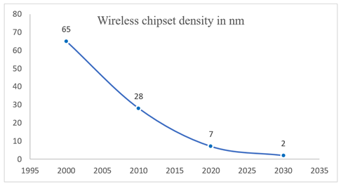
Figure 5
As can be seen from the above figure, 3G utilized 65nm technology for the chipset, 4G utilizes 28nm. For 5G, initial chipset utilizes 7nm technology. The second-generation chipset for 5G will utilize 5nm technology. The increased cost and complexity of the chipset is mitigated by increased chipset sales in each generation. However, the cost of the chipset may still be too expensive for vast of the vertical applications. Furthermore, this level of chipset density makes it prohibitively expensive for any chipset modifications to meet the diverse needs of the vertical applications. For this reason, 3GPP has launched “5G light” effort in the standard process to reduce the complexity and cost for industrial terminals or modules. Will “5G-light” be successful in solving the cost issue for the vertical application modules, only time can tell.
3. Conclusions
5G has made significant progress in user data, transmission delay and system capacity. Although attempts are made to reverse the declining revenue trend for operators by supporting vertical applications, challenges remain formidable in areas of costs, coverage, QoS flexibility, fractured markets, and the maturity of vertical platforms. The success of the millimeter wave deployment may additionally depend on removal of the export restrictions to promote a healthier global ecosystem and to further reduce the system and device costs.
References
- GSMA website, https://www.gsma.com/r/mobileeconomy/
- G.J.Foschini and M.J. Gans, "On Limits of Wireless Communications in a Fading Environment when Using Multiple Antennas", Wireless Personal Communications, vol.6,pp.311-335, 1998.
- Erik G. Larsson ; Ove Edfors ; Fredrik Tufvesson ; Thomas L. Marzetta, “Massive MIMO for next generation wireless systems,” IEEE Communications Magazine, Volume: 52 , Issue: 2 , February 2014.
- M. Dohler; R.W. Heath; A. Lozano; C.B. Papadias; R.A. Valenzuela, “Is the PHY layer dead?” IEEE Communications Magazine, Volume: 49, Issue: 4, April 2011, pp. 159 - 165
- M.2083, "IMT Vision - Framework and overall objectives of the future development of IMT for 2020 and beyond," ITU-R M.2083, 2015.
- Shannon, Claude E. and Warren Weaver. “The Mathematical Theory of Communication.” Urbana, Illinois: University of Illinois Press, 1949.
- Berrou, Claude; Glavieux, Alain; Thitimajshima, Punya, “Near Shannon limit error-correcting coding and decoding: Turbo-codes,” Proceedings of ICC '93 - IEEE International Conference on Communications, May 1993.
- QI BI. Ten Trends in the Cellular Industry and an Outlook on 6G. IEEE Communications Magazine, 2019,57(12): 31-36.
- https://en.wikipedia.org/wiki/Free-space_path_loss
- https://en.wikipedia.org/wiki/COST_Hata_model
- https://www.mobileworldlive.com/featured-content/top-three/docomo-kills-off-nb-iot-network/
- TR21.916, “3GPP Release 16 Description,” https://www.3gpp.org/release-16, July, 2020
- RP-192251, “Proposal on UE requirements to allow switching between two uplink carriers,” Submission to 3GPP TSG RAN #85, Newport Beach, USA, September, 2019.
- P. Popovski et al., “5G Wireless Network Slicing for eMBB, URLLC, and mMTC: A Communication-Theoretic View,” IEEE Access, vol. 6, Sept. 2018, pp. 55,765–79.
Biography
Qi Bi is the Chief Expert of China Telecom with interests in 5G and 6G responsible for technologies, standards and trials. He received his M.S. from Shanghai Jiao Tong University and Ph.D. from Pennsylvania State University.
Previously, Dr. Bi worked at Bell Labs for 20+ years and was awarded the prestigious Bell Labs Fellow in 2002. Other awards included Bell Labs President’s Gold Awards in 2000 & 2002, the Bell Labs Innovation Team Award in 2003, and Asian American Engineer of the Year in 2005. He is an IEEE Fellow, and served in the IEEE Fellow evaluation committee for the communication society in 2017-2019. He holds 47 US patents, 63 European patents and 65 Chinese patents. While in China Telecom, his 4G innovation project was successfully deployed in 75% of China Telecom’s markets and won the GTB Innovation Award at London in 2014.
Subscribe to Tech Focus
Join our IEEE Future Networks Technical Community and receive IEEE Future NetworksTech Focus delivered to your email.
Article Contributions Welcome
Submit Manuscript via Track Chair
Author guidelines can be found here.
Other Future Networks Publications
IEEE Future Networks Tech Focus Editorial Board
Rod Waterhouse, Editor-in-Chief
Mithun Mukherjee, Managing Editor
Imran Shafique Ansari
Anwer Al-Dulaimi
Stefano Buzzi
Yunlong Cai
Zhi Ning Chen
Panagiotis Demestichas
Ashutosh Dutta
Yang Hao
Gerry Hayes
Chih-Lin I
James Irvine
Meng Lu
Amine Maaref
Thas Nirmalathas
Sen Wang
Shugong Xu
Haijun Zhang
Glaucio Haroldo Silva de Carvalho